Steve Dunning, Managing Director of Martindale Electric explains how remembering a simple acronym can help safeguard local authority building and maintenance teams, reduce potential liability and ultimately save lives.
One of the most important responsibilities local authority building maintenance managers have to take on is reducing the risks presented by working with electricity to themselves, employees and the outside contractors they hire. Communication is a key part of this equation — it must be known by all those responsible for, or working with electricity that there are no reasonable circumstances in which you should be working with live equipment.
In an ongoing bid to safeguard workplaces, factories and industrial premises and protect the lives of anyone working on or near an electrical installation Martindale created a simplified version of its more extensive and detailed process in the hope that its memorable acronym — ‘ALIVE’ — will help to prevent injuries and save lives. To aid the communication of these key safety messages, we have made resources and information available to anyone with responsibility for health and safety in an organisation via a specific landing page.
We need to acknowledge that, in terms of the safety of individuals, there is a difference between the activities that should take place prior to working, such as gaining permission and permits, for example, compared to the activities that are totally critical in terms of preventing accidents and fatalities. For instance, a risk assessment is a critical element of any job, but it is not core to safe isolation in terms of staying alive. The same is true for activities that take place after working on an electrical system, such as safe re-testing and start-up.
In creating our ‘ALIVE’ message, we are distinguishing between good working practice (such as our complete 12 step approach and the Electrical Safety Roundtable’s guidelines) and shining a spotlight on the five vital steps that absolutely must be carried out for your own protection and to prevent loss of life.
The 12 step approach will include activities that should certainly take place, particularly in terms of compliance; both sets of processes and procedures are valid and, in fact, complementary, but by streamlining the message and focusing on the most vital elements, following the ‘ALIVE’ process is what will, quite literally, keep you alive.
ALIVE: five fail-proof steps to safe isolation
A — Approved Kit
Before starting, make sure your equipment meets all legal safety standards (BS EN61243-3).
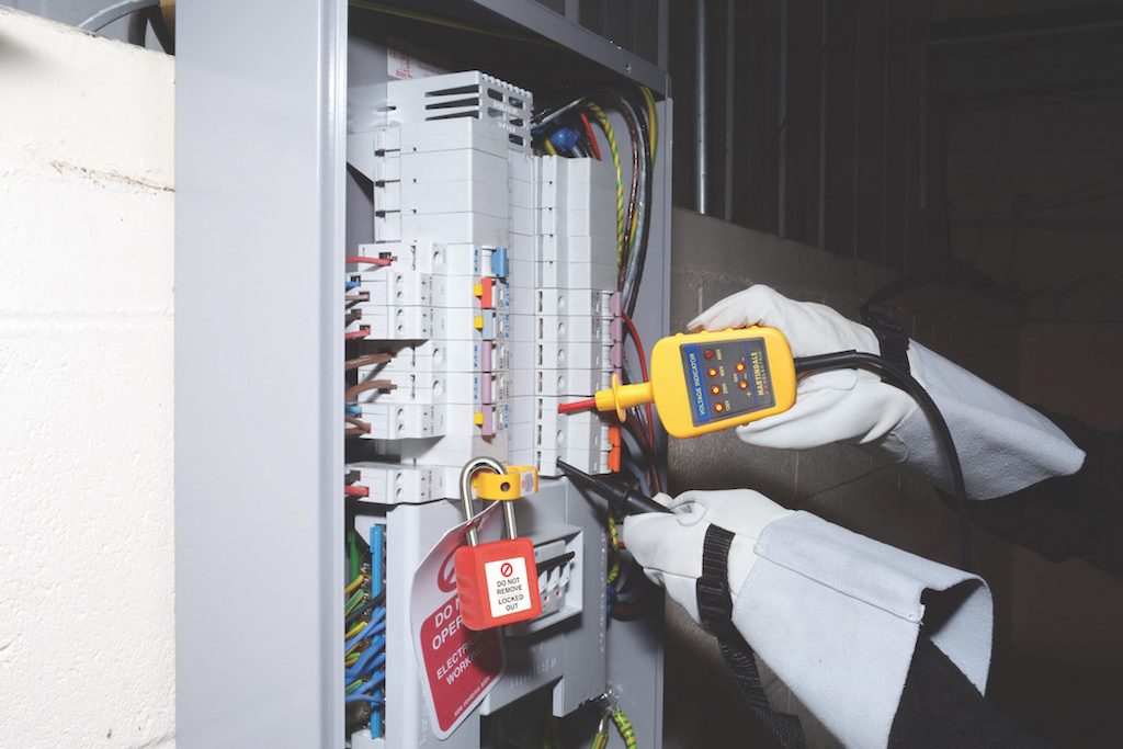
L — Lock Out
Identify the point of isolation — lock it out (off) — and place warning tags onto the equipment.
I — Initial Prove
Test your Voltage Indicator/Tester against the proving unit to make sure that it’s working properly.
V — Voltage Test
Use your Voltage Indicator to confirm that there are no dangerous voltages in the circuit you are about to work on.
E — Ensure
Prove and re-test the Voltage Indicator against the proving unit to ensure it is working, before you start working on the circuit.
The best voltage indicators for safe isolation should be made to BS EN 61243-3 for full compliance with the current GS38 standard. They should be engineered with safety in mind, eliminating batteries and switches that could lead to false indications and come with bright, clear displays for voltage reading, such as the Martindale Electric VI13800 and VI15000 voltage indicators. A durable design that can take some rough handling should also be a consideration.
However, even if you follow this advice and even bearing in mind that voltage indicators are designed with inherent reliability, can you 100% guarantee that your voltage indicator is working correctly every time? It only needs to fail once for the consequences to be potentially disastrous; never forget that 16% of deaths in the workplace are linked to electricity.
Verifying performance
For maximum safety, it is vital to verify the performance of your voltage indicator. It’s as important as confirming that the appliance or circuit being tested is dead, and that there is no possibility of it becoming live while you are working.
Before testing the circuit, voltage indicators should therefore be proved using a proving unit, then test the circuit, and then test the voltage indicator against the unit once again to prove that the tester is still functioning properly. The device will verify the performance of the voltage indicator.
If you use a battery powered voltage indicator then proving the unit is working and the battery is not flat, couldn’t be more important. Furthermore, a lack of positive indication does not always prove absence, which is why the crosscheck with a proving device could quite literally be a lifesaver.
Essentially a proving unit is a portable device that serves as a voltage source designed specifically to verify that voltage indicators are working correctly. Some people still rely on testing electrical test tools, such as voltage indicators, against a live source, but this is not always a safe or convenient option. A proving device has been designed to provide a live source wherever you are working — with no need to leave the working area — and is considerably safer.
![]()
Safer solution
Proving units are very quick and easy to use. In the case of the Martindale PD440S 440V AC proving device, for example, you simply place one probe of the voltage indicator under test into the left-hand socket of the proving unit until it makes contact with the terminal. Then place the other probe into the right-hand terminal of the proving unit and gently press down. This will result in the high voltage indicator illuminating to show the unit under test is functioning correctly.
As an added tip, during testing of your voltage indicator, we recommend flexing the voltage indicator cable along its length — particularly at the entry points to the hand-held elements — to confirm that the cable has not fractured. It is advisable to use a dedicated proving unit matched to the voltage indicator in order to fully test that all LEDs on all ranges of the voltage indicator are working — safeguarding against incorrect readings due to a faulty LED, for example.
Furthermore, it is important not to over-prove: a three-phase voltage indicator should be proved at 440V whereas a common 2-pole indicator with a 690V range should be proved at 690V.
By incorporating a proving device into an electrical safety process, that process becomes inherently more robust and reliable. Although a relatively simple addition to the process, when working with or near electrical systems and equipment, a proving device can significantly reduce the risk of electrical injury to you and others around you.