
Kingspan Technical Insulation discusses the requirements of CP1 Heat networks: Code of Practice for the UK (2020) and the importance of optimising secondary pipe insulation to improve performance and prevent heat loss.
It’s expected that the number of UK homes connected to heat networks will need to rise from around half a million to 5.5 million by 2050 if we’re to reach our net zero targets. These schemes can provide clear advantages for both housing providers and occupants, allowing a smoother transition to low carbon heating sources whilst avoiding the ongoing cost of maintaining or replacing boilers in each home. At the same time, some existing schemes have come under criticism as issues such as gaps in the insulation lagging on services have led to significant bills for occupants — potentially pushing them into fuel poverty.
To support improved practice on these projects, CIBSE has now published a revised version of CP1 Heat networks: Code of Practice for the UK (2020). This document is designed to cover all stages in the development, installation and operation of a network, setting clear checklists for the project team along with 540 minimum requirements. It also actively encourages project teams to look beyond these basic requirements and consider how improvements to areas such as pipe insulation can help to deliver effective operation and the best possible experience for end users.
Why heat networks?
Heat networks are far from a new concept. They essentially comprise an energy centre or centres, which can serve either an individual multi-unit property (communal heating) or multiple properties (district heating).
There are several reasons why they’re now being positioned as a key option for low carbon heating supply. By removing the need for individual heat sources such as boilers or heat pumps to be fitted on each home, they not only reduce the maintenance burden but also help to maximise internal space. This makes them especially well suited for urban areas, particularly as the population density means it is possible to serve a greater number of customers with a smaller pipework network.
Additionally, these networks are ‘fuel agnostic’. This means they can use a range of heat sources. For example, a network may begin using gas before switching to a low carbon technology such as a heat pump. They can also take advantage of local sources such as geothermal energy or, in the case of Islington Council’s Bunhill Heat and Power Network, heat from the London Underground.
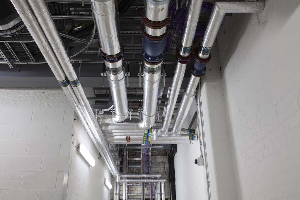
Whilst this centralised approach offers clear advantages, there is also considerable scope for inefficiencies to creep in, particularly in the network of so-called secondary systems, which comprise all the pipework and associated services within a building. In addition to potentially increasing the carbon footprint and energy bills for owners, heat loss from these services can also increase overheating risk in the summer months. For this reason, CIBSE CP1 (2020) specifically addresses how to plan and insulate these services.
Insulating secondary pipework
The minimum thicknesses of insulation for different secondary pipe diameters are provided in Objective 3.9.7 of CP1 (2020). In almost all cases, a 50mm thickness of either phenolic or mineral fibre pipe insulation is suggested. It’s worth emphasising that these values should be treated as minimums and not targets, with the required thicknesses to be calculated as per Objective 3.9.8 of CP1 (2020) based on project specific parameters. In practice, many ESCo’s (Energy Services Companies) heat network schemes already require greater thicknesses of insulation to be used.
Additionally, heat loss from pipework insulated to the minimum requirements in the two materials can vary considerably as phenolic insulation is a notably better insulator than mineral fibre. Modelling has shown that heat losses increase by between 30% – 39% when the CP1 (2020) minimum mineral fibre specification is used in place of its minimum phenolic specification.
For this reason, CP1 (2020) requires calculations for heat losses from pipework to be carried out at the Feasibility Stage (Stage 2) and a detailed insulation specification at the Design Stage (Stage 3). This approach should allow the pipework insulation specification to be carefully tailored to the performance targets for the overall network.
It is also essential that this careful planning is carried through to installation. Even small gaps in the insulation layer on services can lead to considerable heat loss. For example, calculations show that annual heat loss from an effectively insulated 4” valve on a system operating at 75˚C is around 153kWh. If the valve is left uninsulated, that jumps to 2,240kWh. To prevent this, CP1 (2020) emphasises the need for continuous insulation across the system, including all components such as valves and flanges, and recommends fitting ‘rigid low-conductivity inserts’ on pipe supports.
Assured performance
Heat networks offer significant potential to reduce carbon emissions, cut maintenance costs and provide a cheap and efficient source of heating for tenants. By ensuring your installation meets all the minimum requirements of CP1 and taking steps to carefully consider how areas such as secondary pipe insulation can be further optimised, it should be possible to ensure the system delivers on these promises.